Troubleshooting Guide
See below for a list of common questions and troubleshooting topics.
If you can’t find what you’re looking for, contact us.
ELECTRICAL SYSTEM GUIDE ET PROPORTIONAL
ET PROPORTIONAL: 3516E, 4020E, 4520E
ELECTRICAL SYSTEM GUIDE ET NON-PROPORTIONAL
ET NON-PROPORTIONAL: ET8KX-14 & ET12KX-15
ET NON-PROPORTIONAL: 3215E, 3515E, 4016E, 4516E
Venturo 3215E/3515E/3516E Installation Instructions
Venturo 3215E/3515E/3516E Installation Instructions
Venturo 3215E/3515E/3516E Crane Installation Instructions
1. Safety Precautions
-
Inspect vehicle and crane thoroughly before installation.
-
Work only on firm, level ground.
-
Always wear appropriate personal protective equipment (PPE).
-
Disconnect the vehicle battery before electrical work: First, turn off the vehicle ignition and remove the keys. Locate the battery, typically found under the hood or in a side compartment. Using an appropriate wrench, loosen the nut on the negative (black) terminal and carefully remove the cable, ensuring it is secured away from the battery. Repeat for the positive (red) terminal if needed. Confirm that no electrical devices are active before proceeding.
-
Refer to all safety decals and warnings provided with the crane.
2. Base Mounting
-
Ensure the truck frame is suitable for crane mounting: Inspect the frame for structural integrity, checking for cracks, corrosion, or damage. Confirm that the frame is level and capable of supporting the crane’s weight. Measure and mark the mounting points per the provided installation dimensions. Verify that the frame material meets the manufacturer’s specifications for strength and thickness.
-
Use 4x 7/8″ Grade 8 mounting bolts, ensuring they are clean and free of debris, and torque them to exactly 455 ft-lbs using a calibrated torque wrench. Apply an anti-seize compound to the bolt threads before installation to prevent galling. Tighten bolts in a crisscross pattern to ensure even pressure distribution and verify torque with a final check after installation.
-
Reinforce the mounting area according to the provided reinforcement diagram: Position the reinforcement plates as shown in the diagram, ensuring they align with the mounting bolt holes. Weld or bolt the reinforcement plates securely to the truck frame. Inspect the welds for cracks or defects. Confirm that the reinforcement area is level and free of debris before proceeding with crane installation.
3. Battery and Cable Installation
-
Use a 12V auxiliary battery with a minimum of 625 CCA (Cold Cranking Amps). Ensure the battery is fully charged and properly secured. Inspect battery terminals for corrosion and clean them if necessary. Connect the battery using appropriate cables, ensuring proper polarity: positive (+) to the power terminal and negative (-) to the ground. Verify battery output with a multimeter if unsure of its condition.
-
Install #2 gauge cables for both power and ground: Route the cables along the designated cable path, securing them with insulated clamps every 12 inches to prevent chafing. Crimp heavy-duty ring terminals on each cable end using a hydraulic crimping tool. Attach the power cable to the positive terminal on the crane’s power input and the ground cable to a solid, clean grounding point on the truck frame. Use heat-shrink tubing to cover all exposed connections for protection against moisture and corrosion. Verify the cable polarity and continuity with a multimeter before powering up.
-
Connect the master disconnect switch between the truck battery and the crane: Mount the switch in a location easily accessible to the operator. Use #2 gauge cables to connect the positive terminal of the truck battery to the input terminal of the switch. Connect the output terminal of the switch to the crane’s power input. Secure all connections with heavy-duty ring terminals and cover them with heat-shrink tubing. Tighten all terminal nuts securely and ensure proper polarity. Label the switch clearly as “Master Disconnect.”
-
Follow the wiring diagram for proper connections: Connect the positive cable from the master disconnect switch to the crane’s power input terminal. Connect the ground cable from the truck frame to the crane’s grounding terminal. Attach the control wiring harness according to the color-coded diagram, ensuring that each terminal corresponds to its designated function (e.g., winch up, boom extension, overload alarm). Secure all connections with insulated clamps and cover exposed terminals with protective caps. Conduct a continuity test to confirm proper wiring before powering on the system.
4. Stability Testing
-
Fully deploy stabilizers by extending them completely until they lock securely. Ensure each stabilizer pad makes full contact with firm, level ground. Use stabilizer pads or blocks if the ground is soft to distribute the load evenly. Visually check that the truck remains level and stable before proceeding with further operations.
-
Use a test weight between 941 lbs and 1000 lbs: Select a certified test weight that falls within this range. Secure the test weight properly to the crane’s hook using a rated sling or shackle. Ensure the area is clear of personnel before lifting. Lift the weight slowly to about 6 inches above the ground and maintain the lift for at least 30 seconds to observe stability. If any instability occurs, lower the weight immediately and adjust the setup before retesting.
-
Perform the stability test per ANSI B30.5 standards: Follow the ANSI B30.5 guidelines step-by-step, ensuring the crane is on level ground with stabilizers fully deployed. Use the designated test weight and rotate the crane through all specified positions, holding each position briefly to observe stability. Document any signs of tipping or imbalance and adjust the setup if needed. Record all measurements and observations in accordance with ANSI B30.5 reporting requirements.
-
Record results in the provided stability chart: Include detailed entries for each test position, noting boom angle, reach distance, and load weight. Document any observed stability issues, adjustments made, and pass/fail outcomes. Sign and date the chart, ensuring it is complete and ready for review.
5. Wire Rope Installation
-
Unroll the wire rope carefully to avoid kinks: Lay the coil on a flat surface and roll it out straight, maintaining gentle tension to prevent loops from forming. Do not pull the rope from the side of the coil, as this can cause twists and kinks. Inspect the rope for any frays or damage as you unroll it. Use gloves to protect your hands from wire splinters.
-
Feed the rope through the anti-two-block device and the top sheave: Begin by aligning the rope with the entry point of the anti-two-block device. Guide it carefully through the device’s rollers, ensuring smooth passage. Continue feeding the rope over the top sheave, keeping it taut to prevent slack or twisting. Confirm that the rope runs evenly within the sheave groove without overlapping or jumping out of alignment.
-
Secure the rope to the winch drum with a wedge: First, insert the rope end through the anchor pocket on the winch drum. Wrap the rope around the wedge and feed it back through the pocket, ensuring it is firmly seated. Tighten the wedge securely, making sure the rope is clamped tightly. Rotate the drum manually to wind the rope evenly. Ensure at least five full wraps remain on the drum, as these wraps are critical for holding the load securely.
6. Initial Operation Check
-
Plug in the remote pendant: Align the connector with the socket and push it in firmly until it clicks into place. Secure the strain relief tether if provided. Turn on the master disconnect switch by rotating it to the ON position or flipping the lever, ensuring a solid connection. Verify that the crane control system powers on by observing indicator lights or a status display, if equipped.
-
Test all crane functions: winch, boom extension, elevation, and rotation. For each function, operate the controls slowly at first to observe for any unusual sounds or movements. For the winch, verify smooth spooling and proper tension control. For the boom extension and elevation, check for smooth travel and proper stopping points. During rotation, ensure a full range of motion without binding or hesitation. Test emergency stops for each function to confirm safety features are operational.
-
Verify the overload sensing system by simulating an overload condition: Gradually increase the load beyond the rated capacity using a test weight. Observe for automatic shutdown of winch-up, boom-down, and boom-out functions, as the system should engage to prevent overload. If the crane is equipped with an overload alarm, verify that it sounds during the test. Use the winch-down or boom-in controls to relieve the overload condition. Document the results and ensure proper system reset after the test.
7. Final Preparations
-
Stow the boom properly and secure the winch line: Lower the boom into the designated stow cradle or support bracket. Lock the boom into position using the boom latch or securing pins if provided. Wind the winch line tightly onto the drum and attach the hook to the designated tie-down point on the frame or support bracket. Apply slight tension to the winch line to prevent slack or unraveling during transport.
-
Ensure all safety decals are in place, clean, legible, and securely affixed in their designated locations. Inspect each decal for damage or fading and replace if necessary. Confirm that critical warnings, such as electrical hazard and capacity limits, are positioned where they are easily visible to the operator.
-
Provide the operator with the Venturo Safety Manual: Hand-deliver the manual and review key sections, including safety precautions, operational procedures, and emergency protocols. Ensure the operator acknowledges receipt and understands the importance of regular reference to the manual for safe operation.
For further details, refer to the complete Venturo Electric-Hydraulic Cranes Owner’s Manuals.
Installation of Venturo 25100/25500 Outriggers on Falcon Crane Body
Install Instructions
Installation Instructions: Venturo 25500-PHX-SL & 25500-PHX-LL Outriggers on Falcon Crane Body
- Preparation and Safety Considerations
Pre-Installation Inspection
Before starting, thoroughly inspect the outrigger kit and the crane body. Verify all required parts are on hand (refer to the Parts List in Appendix) and check each component for shipping damage or defects. No modifications should be made to any outrigger components – use only the supplied parts and hardware as intended. Examine the Falcon crane body’s rear frame area where the outriggers will mount, ensuring it is free of deformation, heavy rust, or obstructions. If the crane is already installed, make sure it is properly secured and the truck is parked on a level, hard surface before proceeding.
Required Tools and Equipment
Gather the necessary tools and equipment for installation:
- Lifting Equipment: A hoist, crane, or jack to raise the heavy crosstube into position.
- Fastening Tools: A wrench and socket set (including 5/8″ and 3/4″ sizes), Allen/hex keys (if required), and a calibrated torque wrench capable of up to ~200 ft-lb.
- Drilling/Welding Equipment: An appropriate welding machine (with electrodes or wire suited for structural steel) for attaching brackets, and a drill with metal bits (if holes in chassis or body need to be added).
- Hydraulic Tools: Hose wrenches, thread sealant (as specified by Venturo), and hydraulic fluid (matching the crane’s system) for topping off.
- Measuring and Marking: Tape measure, straightedge, and markers to position components accurately.
- Personal Protective Equipment (PPE): Safety glasses, work gloves, steel-toe boots, and a welding helmet/protective clothing for welding tasks.
Ensure all tools are in good condition and rated for the job. Having an assistant or a second technician is highly recommended due to the size and weight of the stabilizer components.
Safety Protocols
Always follow standard shop safety practices during the installation. Disconnect the vehicle’s battery and, if applicable, the hydraulic pump power before welding or electrical work to prevent damage or injury. If using a crane or hoist to position the crosstube, make sure the lifting straps or chains are rated for the load and securely attached. Support the truck with jack stands or cribbing if you will be working underneath, and chock the wheels to prevent any movement. When welding on the chassis or outriggers, keep a fire extinguisher nearby and clear away any flammable materials. Maintain proper ventilation during welding.
When handling heavy components like the crosstube and legs, use proper lifting techniques and avoid placing your hands or limbs where they could be pinched. Wear PPE at all times – especially eye protection when grinding, drilling, or welding, and gloves when handling rough or hot metal. Never work under a suspended load; secure components in place before positioning yourself beneath them. Finally, adhere to all OSHA lockout/tagout procedures if working on or around energized hydraulic systems – ensure the crane’s hydraulic system is de-pressurized and the engine (or hydraulic pump) is off before connecting hoses. A careful, methodical approach to safety and preparation will set the stage for a successful outrigger installation.
- Mounting the Crosstube (Standard Configuration)
In the standard configuration (with a full-width crosstube included), the stabilizer crosstube must be mounted at the rear of the Falcon crane body and secured to provide a solid base for the outrigger legs. Proper positioning, attachment, and clearance are critical to ensure stability and safe vehicle operation.
Proper Positioning and Alignment
Orient the stabilizer correctly: The 25500-PHX outriggers have one pullout section longer than the other – mount the crosstube such that the longer sliding pullout is on the crane side of the truck. This orientation allows the crane-side outrigger to extend further out for better support. Center the crosstube laterally at the extreme rear of the truck so that it spans equally across the left and right sides of the chassis. The crosstube should sit directly behind (or below) the rear edge of the crane body, tight to the rear of the cargo bed but not protruding beyond the truck’s tail when retracted.
Align with chassis and body structure: Position the crosstube so that it is tied into the truck’s frame rails, the body longsills, and the crane pedestal/support structure. In other words, the crosstube should make solid contact with (or be bracketed to) the main structural members: the two chassis frame rails and the reinforced longitudinal sills of the crane body. This may require fitting spacer plates or brackets to bridge between the crosstube and frame if there is a gap. Make sure the top of the crosstube is level and at the appropriate height relative to the truck frame so the stabilizer legs will contact the ground properly when deployed.
Welding and Bolting Attachment
Use structural brackets and supports: Do not directly weld the crosstube to thin body sheet metal or unsupported sections of the service body. Instead, use robust structural members or brackets to attach it. Venturo recommends using 8″ structural channel or similar heavy gauge steel as a shear plate bracket between the crosstube and truck frame. For example, you can weld a short segment of channel iron vertically to each end of the crosstube and then bolt that channel to the side of the chassis frame rail (as illustrated above). Likewise, weld or bolt the crosstube to the body longsills (the structural C-channels running fore-aft under the body floor) so that the load is shared by the crane body’s structure. The installer is responsible for fabricating or supplying any such mounting brackets or gussets as needed for the specific body – ensure all fabrication steel is of equivalent strength and is properly cut to fit.
Follow proper welding procedures: Prior to welding, grind off any paint or coatings on the crosstube and crane body attachment areas to ensure a clean weld. Weld using an appropriate process and filler (e.g. MIG or stick with E70XX rod) with sufficient bead size to develop the full strength of the material. Venturo’s guidelines mark specific “suggested welding locations” on the bracket (see wavy weld symbols in the figure) which are typically along the seams where the crosstube meets the bracket plate【47†】. Make continuous fillet welds of adequate length on both sides of each bracket. If bolting is also used, drilling holes through the chassis frame should follow the truck manufacturer’s upfitter guidelines (avoid drilling in high-stress flange areas, etc.). Use grade 8 bolts (5/8″-11) with lock nuts if bolting the crosstube or bracket to the frame, and torque them to spec (approx. 150 ft‑lb – see Appendix for torque specs). On a Venturo-supplied Falcon crane body, there may be pre-engineered mounting provisions or factory-installed weld nuts to accept the stabilizer – if so, align and attach per the body manufacturer’s instructions.
After welding, allow everything to cool slowly (do not quench with water). Inspect the welds for good penetration and tie-in. Do not weld the stabilizer directly to thin body panels or unsupported sheet metal; all attachments should be into substantial structural members to ensure the stabilizer can support the crane loads without deforming the body. If needed, add gusset plates or additional brackets to reinforce the connection between the crosstube and the crane body or frame. The goal is a rigid installation with the crosstube effectively becoming part of the rear structure of the truck.
Required Clearances and Departure Angle
Leg retraction clearance: When positioning the crosstube vertically, allow adequate clearance so that the stabilizer legs can fully retract into the stowed (up) position without hitting the underside of the body. There should be a gap between the top of each leg and the crane body floor or any bumper structure when the legs are folded up. Typically a few inches of clearance is recommended to account for any flex. If the Falcon body has outrigger cut-outs or notches, ensure the crosstube is aligned with those. Also verify that any bumpers, lights, or other fittings at the rear of the body won’t interfere with the outrigger swing or leg deployment.
Maintain a proper departure angle: It is crucial that the installed outriggers do not excessively reduce the truck’s ground clearance at the rear. When the legs are fully retracted and stowed, aim for at least a 15° departure angle between the horizontal ground and a line drawn from the bottom of the rear tire to the lowest point of the stabilizer assembly. This means the bottom of the stowed outrigger (usually the foot or lower leg) should be well above the plane of the rear tires’ contact patch. In practical terms, the outrigger feet should sit several inches higher than the lowest point of the rear tires. This clearance prevents the outriggers from dragging or impacting the ground when the truck traverses ramps or uneven terrain. Adjust the vertical mounting position as needed to achieve this angle – on most crane bodies, mounting the crosstube just below the body floor yields roughly the recommended 15°.
After securing the crosstube, double-check this departure angle: with the truck on level ground, measure or sight the angle from the rear tire to the outrigger foot. If it’s less than 15° (too low), consider raising the crosstube or trimming obstructions. Ensuring the proper departure angle is not only important for off-road clearance but is also often required by DOT regulations and Venturo’s guidelines for safe operation.
Lastly, consult the truck manufacturer’s Body Builder/up-fitter manual regarding any specific instructions for welding to or drilling the chassis frame. Many chassis have restrictions on frame modifications. Use grade 8 fasteners and proper techniques as specified by the chassis OEM when bolting to the frame. With the crosstube correctly mounted—centered, secured to the frame and body, and with proper clearances—the foundation is set for assembling the outriggers.
- Installation of “Less Crosstube” (LCT) Configuration
Venturo offers the 25500-PHX stabilizer in a “-LC” or Less Crosstube configuration, meaning the cross tube and stabilizer components are shipped in pieces to be assembled on the truck. If your outrigger package was ordered in this LCT configuration (common when retrofitting to an existing body), follow these assembly steps before mounting to the truck. (Per Venturo, LCT packages will have certain parts shipped loose that require assembly by the installer.) Ensure you have all the LCT-specific parts ready, including the UHMW wear pads, nut bar retainers, hydraulic tubing, bulkhead fittings, and the hydraulic pullout cylinder with its housing and shaft.
Assembly Steps for LCT Outriggers:
- Install UHMW Pads: Locate the Ultra-High-Molecular-Weight (UHMW) polyethylene wear pads (Part #25081). Place one pad on the pullout slider tube (the telescoping section that goes inside the crosstube) and the other pad inside the crosstube’s interior channel. These slick pads will line the sliding surfaces to reduce friction. Ensure they are positioned per the Venturo diagram (usually at the top/bottom of the channel where the pullout will contact). They may be held in with screws or adhesive as provided – secure them so they won’t shift during operation.
- Insert the Pullout Assembly: Make sure the hydraulic pullout cylinder housing (the square tubing that holds the horizontal hydraulic cylinder) and its attached hoses/tubes are still tied together with shipping straps or wire at this stage(this prevents them from flopping). Then slide the pullout assembly into the crosstube from one end. This is the telescoping action: feed the smaller slider tube (with the cylinder inside) into the larger fixed cross tube. It may be a tight fit – ensure the UHMW pads remain in place and guide the pullout straight in so as not to gouge the pads. Slide it all the way until centered (the pullout should be roughly equal length protruding on both sides of the crosstube when retracted).
- Secure Nut Bar Retainers: Inside the crosstube, you will use the provided nut bar retainers (Part #25065 and #25077) to lock the pullout in place and provide threaded attachment points for other hardware. There are two shorter retainers (#25065) and one longer retainer (#25077) in the kit. Position and fasten the two 25065 nut bar retainers inside the crosstube as indicated (these typically sit at the outer ends of the crosstube). Then install the single 25077 nut bar retainer in the crosstube (usually centered). Use the supplied 5/16″-18 bolts, lock washers, and flat washers (Parts #HHCS03118075, #LWSH-031, #FWSH-031) to bolt these retainers in place through pre-drilled holes in the crosstube. Tighten these small bolts snugly (approximately 17 ft‑lb for 5/16″ Grade 5 hardware). The nut bars will serve as internal nuts for the outrigger leg mounting bars and other components later. Ensure each retainer is aligned with its bolt holes and is flush inside the tube.
- Install Bulkhead Fittings and Hydraulic Tubes: The stabilizer’s hydraulic plumbing is partly pre-routed with rigid tubing that runs inside the crosstube to the cylinders. First, fasten the bulkhead fittings into the designated holes on the crosstube. There are typically four 90° bulkhead adapters (Part #H2701-0606, 6MJ-6MJ) – two for the horizontal pullout cylinder and one for each vertical leg cylinder. Secure each fitting with its bulkhead nut (tighten firmly so they won’t leak or loosen). Next, take the long hydraulic tubes (60″ and 47″ lengths, Parts #25138 and #25139) and insert them through the crosstube, connecting them to the bulkhead fittings as per the assembly diagram. The tubes route the hydraulic fluid from the bulkheads to the cylinders. Push rubber grommets (Part #14883) into the holes where the tubes pass through any openings in the crosstube or cylinder housing– these grommets protect the tubes from chafing. Then clamp the tubes in place using the provided clamp plates (Part #25157) and 3/8″-16 bolts with washers (#HHCS03816050, etc.). Tighten the 3/8″ Grade 5 bolts to roughly 30–35 ft‑lb to secure the tube clamps. Ensure the tubing is not kinked and that the bends match the intended routing. At this stage, do not yet untie the hoses/tubes that were secured – leave them tied until the final hookup to avoid strain.
- Mount the Pullout Cylinder Shaft: With the pullout assembly fully inserted and centered, it’s time to lock the horizontal (extend/retract) cylinder in place. The kit includes a large cylinder shaft (Part #25051) and two split shaft collars (Part #28446). This steel shaft is inserted through the top slot of the crosstube and through the pullout cylinder housing. Remove any shipping ties now from the cylinder housing and plumbingso that you can maneuver the parts. Then insert the 3/4″ diameter shaft through the aligned holes: slide it through one side of the crosstube, through the top of the cylinder housing (there is a matching hole in the cylinder’s mounting lugs), and out the other side of the crosstube. Once the shaft is centered, place a collar on each end of the shaft, flush against the crosstube. Apply a threadlocking compound (e.g. Loctite) to the collar clamp screws, then fasten the collars securely to lock the shaft in position. The collars will clamp onto the shaft, preventing it from sliding out. Tighten the collar screws firmly (they are small, but ensure they bite into the shaft). The shaft and collar assembly fixes the horizontal cylinder housing in the crosstube so that when the cylinder extends, it forces the pullout tube to slide, rather than just pushing itself out of the tube. Double-check that the cylinder can pivot slightly on this shaft (it should act as a hinge) and that the collars are tight.
With these steps completed, the “less crosstube” stabilizer assembly is now fully put together as it would be in the standard configuration. Proceed to mount the assembled crosstube to the truck frame and body as described in Section 2 above. The remaining steps (mounting the legs and hooking up hydraulics) are the same for both configurations. All critical LCT components – the UHMW pads, retainers, tubes, and shaft – should now be installed as per Venturo’s assembly drawings. Take a moment to review everything: all bolts used in the assembly are tight, the pullout slider moves freely in the crosstube without binding (you can manually extend/retract it to test), and the cylinder hoses/tubes align with the bulkhead fittings without twisting. Any loose shipped items (as noted by Venturo) should now be installed. You can now move on to attaching the stabilizer legs.
- Mounting the Stabilizer Legs (SL and LL)
With the crosstube and pullout mechanism in place on the truck, the next step is to install the two stabilizer leg assemblies. The 25500-PHX outriggers come in two leg length options: Short Leg (SL) and Long Leg (LL). The installation process is identical for both; the only difference is the range of vertical adjustment and the cylinder stroke length. The short legs provide ~14″ of vertical travel, whereas the long legs provide ~24″ of travel, to accommodate higher mounting heights. Each leg assembly consists of a hydraulic jack leg with a swivel foot pad and mounting brackets on top. They will attach to the ends of the crosstube (or the pullout end pieces) via the supplied mounting plates and hardware.
Leg Positioning and Adjustment Range
Before bolting on the legs, decide on the vertical mounting position for each leg. There are multiple mounting holes on the leg bracket and matching holes on the crosstube’s mounting adapter plate, which allow the leg’s height to be adjusted in 2″ increments. This ensures you can achieve the proper ground contact without overstroking the cylinder. For Short Leg (SL) versions, there are 7 mounting positions (14″ total range) available. For Long Leg (LL) versions, there are 12 positions (24″ range). Typically, you should mount the legs in the lowest position that still allows a few inches of ground clearance when retracted. The goal is that when the legs deploy, they can extend 4–6″ downward to press on the ground (compressing the truck’s suspension slightly). If mounted too high, the legs might not reach the ground; too low and they could hang too near the ground when stowed. As a starting point, Venturo’s installation drawings show an example with the leg pinned about mid-range (e.g. ~19½″ down from top for SL, ~29½″ for LL) which gives the desired 4–6″ stroke remaining when on level ground. Measure from the bottom of the truck body to the ground and choose a hole position that best matches your needed leg extension.
Leg Mounting Procedure
Each stabilizer leg attaches to a mounting adapter plate that is either welded or bolted to the ends of the crosstube (installed in Section 2). In a Falcon crane body, these adapter plates may have been pre-welded in the proper spot at the rear corners of the body or on the pullout ends. The stabilizer leg assembly has a matching leg mounting bar or bracket at its top. To install the legs:
- Align the leg with the adapter plate: Position the leg assembly against the mounting adapter plate at the chosen height. The leg’s mounting bracket (often a pair of flanges with holes) should line up with the corresponding holes in the adapter plate. Ensure the leg’s hydraulic cylinder ports face inward or as specified (Venturo labels the port orientation – typically the “EXTEND” port is oriented to the outside and “RETRACT” port to the inside on each leg for hose routing). Also, verify the leg is oriented so that the swivel foot is facing the correct direction (usually straight down or slightly outward) and that the Danger decal location (to be applied) will be visible.
- Insert mounting hardware: Slide the leg mounting bar or pin into place between the two plates. In Venturo’s design, this is accomplished by bolting through the plate and leg bracket. Use the provided four 3/4″-10 x 3″ hex head cap screws (Grade 5) and four 3/4″-10 full-height nylon-insert lock nuts (Grade 5). Insert the bolts through the aligned holes (two on each side of each leg) and thread the lock nuts on the inside. This hardware clamps the leg’s mounting bar to the adapter plate. Ensure all four bolts are installed with washers as provided (if any) and that the leg is still free to pivot up and down (the brackets should not be distorted or binding).
- Torque the mounting bolts: Tighten the 3/4″-10 bolts evenly and securely. Venturo specifies torquing these leg mounting bar bolts to 100 ft‑lb. Use a torque wrench to ensure each of the four fasteners on each leg is tightened to this specification. The Grade 5 lock nuts will prevent loosening, but it’s good practice to re-check the torque after initial use of the outriggers. Properly tightened, the legs should feel solidly attached with no excessive play, yet able to pivot.
- Attach warning decals: Once the legs are mounted, apply the supplied “DANGER – Crushing Hazard” decal (Part #24964) to each leg. The decal should be placed on the outside face of each leg (one on each) in a visible location, as illustrated in Venturo’s manual. Clean the surface and firmly stick the decal so that it warns operators to keep clear of the leg during operation. Ensure any other required safety or capacity decals are also in place per the manufacturer’s instructions.
After mounting, test the leg pivot action: swing the legs up and pin them (if a transport lock pin is used) or verify they stow fully without contacting the body. Then swing them down – they should move freely. If the Falcon body has leg travel-limiting brackets or catches, make sure they engage properly. Also confirm that at full retraction, the foot of each leg sits about 4–6″ off the ground (on level ground), indicating that when extended it will press down that distance to stabilize the truck. If this gap is significantly different, you may adjust the mounting hole position accordingly.
Cylinder Stroke and Foot Setup
The stabilizer legs come pre-assembled with their hydraulic cylinders and swivel foot pads. For reference, the Short Leg (SL) cylinder has a 20″ stroke and the Long Leg (LL) cylinder a 30″ stroke. This stroke, combined with the adjustable mounting positions, gives the total available travel. The swivel foot on each leg should be pinned or bolted securely to the bottom of the leg – verify that the retaining pin/bolt is in place so the foot cannot drop off. The foot should be able to pivot to sit flat on the ground at various angles; make sure it swivels freely.
If not already done, fill each leg’s cylinder with hydraulic fluid (they are usually shipped filled, but check your manual). There may be a transport plug in the hose ports that needs to be replaced with the actual hose fittings – we will do that in the hydraulic hookup section next. At this stage, the mechanical installation of the legs is complete: they are bolted on with correct torque, positioned for proper range, and labeled with safety decals.
- Hydraulic System Setup
With the outriggers physically installed on the truck, the final installation step is integrating the hydraulic system that will power them. The 25500-PHX outriggers are full hydraulic (hydraulic extension and hydraulic jack legs), and they are designed to tie into the truck’s existing crane hydraulic circuit via a selector valve. The kit includes a dedicated outrigger control valve bank (3-spool) and a selector/diverter valve to switch between crane and outrigger operation. In this section, we will route the hoses, install the valves, and make all necessary connections. Always work clean – keep dirt out of the hydraulic lines, and use thread sealant on fittings as appropriate (use pipe thread tape or liquid sealer only on NPT threads, not on O-ring or JIC fittings).
Overview: The hydraulic setup consists of a selector valve that selects either “Crane” or “Outriggers” mode, and an outrigger valve bank that actually controls the cylinders. The selector valve has one inlet (pressure supply from the pump) and two outlets (one to feed the crane’s control valve, and one to feed the outrigger control valve). By shifting the selector, the operator can direct flow to either the crane or the outriggers, preventing simultaneous operation. The outrigger control valve is a manual 3-spool valve with levers that control: Right Leg Up/Down, Left Leg Up/Down, and Pullout Extension/Retract. Each spool has two work ports (extend and retract) which we will connect to the corresponding cylinder ports. The return from the outrigger valve typically tees into the crane’s return line back to tank (or goes to a common return manifold).
Follow these steps to set up the hydraulic circuit:
- Install the Selector Valve: Locate the Venturo-supplied selector valve (Part #27783) and its mounting bracket (Part #27784). Choose a mounting location for the selector valve – usually on the truck frame or inside a compartment near the crane’s hydraulic control valve. It should be accessible for operation and plumbing. Bolt the bracket securely to the chosen location (the bracket has holes for 3/8″ hardware). Then attach the selector valve to its bracket using the bulkhead nut on the valve stem or other provided fasteners. The valve should be oriented such that the lever can move freely and the positions (Crane/Outrigger) will be clear. Venturo’s valve typically is a 3-position valve: one direction routes flow to “Crane”, the opposite to “Outrigger”, and the center is “Closed”. The valve body is usually labeled accordingly (or has port markings for each circuit). Verify the label or lever positions: “CRANE – OUTRIGGER – CLOSED”. Ensure the lever is installed on the selector valve (if it shipped loose, attach it now, aligning with the keyed shaft as per instructions).
- Plumb the Pressure Supply and Return: Identify the hydraulic pressure supply line coming from the pump (or PTO) that originally fed the crane control valve. This line must be rerouted into the new selector valve’s inlet. Typically, you will disconnect the pressure inlet on the crane’s valve bank and instead connect that hose to the “Supply” port of the selector valve (using appropriate adapters – e.g., the kit includes adapter fittings such as 8MJ-8MO to match hose ends). Then run a new hose from the selector valve’s “Crane” output port back to the crane’s control valve inlet (essentially inserting the selector in series). Likewise, connect a high-pressure hose from the selector valve’s “Outrigger” output port to the inlet of the outrigger valve bank (installed in the next step). Use hydraulic hoses rated for the crane’s system pressure (typically 2500-3000 PSI) and of adequate diameter (1/2″ or as specified by Venturo). Tighten all connections securely. For return lines: if the selector valve has a dedicated return (some are closed-center type and may not require a separate return in neutral), follow Venturo’s schematic. In many cases, the crane and outriggers share a common return line to tank. If so, ensure the outrigger valve’s return is tied into the crane’s return line or directly to tank with minimal back pressure. Do not plug any provided tank ports, as that could deadhead the pump.
- Mount the Outrigger Valve Bank: The outrigger control valve (Part #25050, 3-spool block) needs to be mounted in a convenient location for the operator, often near the rear of the truck or on the side of the crane body. Some Falcon crane bodies have a pre-cut opening or bracket for the outrigger controls. Mount the valve bank securely using bolts on a bracket or directly to a structural surface. Orient it so that the control levers move in a logical direction (Venturo labels the valve functions typically A through F for the six motions: A/B for one leg, C/D for pullout, E/F for the other leg). Often, label the levers or install the decals that indicate “Right Outrigger Up/Down,” “Left Outrigger Up/Down,” and “Outrigger Extend/Retract” to avoid confusion. Once mounted, connect the pressure inlet of this valve bank to the hose coming from the selector valve “Outrigger” port (from step 2). Also connect the valve’s return (outlet) into the crane’s return line or hydraulic reservoir as discussed.
- Connect Hoses to the Stabilizer Cylinders: Now plumb the working lines from the outrigger valve to each cylinder. There are three double-acting cylinders in this system: Right Leg, Left Leg, and Pullout. Each spool of the valve bank has two work ports (one pressurizes extend, one pressurizes retract). Use the bulkhead fittings and rigid tubes installed earlier as termination points for your hoses at the crosstube. For each cylinder: connect one hose from its extend port bulkhead to the corresponding extend port on the valve, and another hose from its retract port bulkhead to the corresponding retract port on the valve. Venturo provides guidance on port identification: the stabilizer is marked with groups of “EXTEND PORTS (3X)” and “RETRACT PORTS (3X)”. Typically, the extend ports correspond to cylinder base ends (leg extends down, pullout extends out) and retract ports to rod ends (leg retracts up, pullout retracts in). For example, on the right leg cylinder, the hose from the “Right Leg Down” valve port (function A) should go to the base port of the right leg cylinder (via the bulkhead). The hose from the “Right Leg Up” valve port (function B) goes to the rod-end port of that cylinder. Repeat for the left leg (functions E = down, F = up) and for the pullout cylinder (C = extend out, D = retract in). It is crucial to get the hoses matched to the correct ports so that the control levers operate in the intended direction. Using the letter labels: connect A to the right leg’s extend port, B to right leg retract; C to pullout extend, D to pullout retract; E to left leg extend, F to left leg retract. If Venturo’s valve or manual includes color-coding or numbering, follow that scheme. Use new hydraulic hoses of appropriate length to reach from the valve to the crosstube bulkhead fittings. Route the hoses along the chassis or underside of the body, securing them with clamps or zip ties so they are protected from moving parts and road debris. Avoid sharp bends and keep hoses away from exhaust components or edges that could chafe them. Where hoses pass through holes, use grommets or abrasion sleeves.
- Selector Valve Operation Check: After plumbing, double-check the selector valve function. In “Crane” mode, the crane’s own hydraulic valve should have pressure and the outrigger valve bank should be isolated (no pressure). In “Outrigger” mode, the outrigger valve gets pressure and the crane valve is isolated. The center “Closed” position should cut off flow to both (used when switching modes). Ensure the selector’s lever positions correspond correctly – Venturo’s selector may have an indicator: e.g. lever in one detent for crane, opposite for outriggers. Also verify the port labeling on the selector (often stamped as “P” for pressure, “C” for crane, “O” for outrigger, etc.) to confirm you connected the hoses to the right ports. Mis-plumbing the selector could result in no flow or continuous flow to both circuits, so take time to verify.
- Finalize and Test for Leaks: Once all connections are made, ensure all fittings (especially those at the cylinder bulkheads and valve ports) are tight. Slowly fill or top off the hydraulic reservoir of the crane’s system with the recommended fluid, since the outrigger cylinders and hoses will consume some fluid. If your system has manual shutoff valves or an electric solenoid, open the flow to the new circuit. At this point, it’s wise to conduct a controlled test (see Final Checks in the next section) to bleed air from the lines and check for leaks. Keep the selector in “Outrigger” mode and have an assistant start the truck’s PTO/hydraulic pump at idle. Operate each outrigger function a few times (extend/retract, leg up/down) to purge air. Observe all hoses and fittings under pressure – tighten any that show slight seepage (with the pump off and pressure relieved). Do not stand directly over fittings while pressurizing; use a piece of cardboard to detect leaks if needed. After initial cycling, re-check the hydraulic fluid level and top off as necessary.
By following the above steps, the outrigger hydraulic circuit should be fully integrated. The crane and outrigger hydraulic circuits are now separated by the selector valve – engaging one will disengage the other as a safety measure. All outrigger functions should be controlled by the new valve bank, and the crane’s controls remain unchanged except for the addition of the selector. Ensure all hoses are neatly routed and clamped, with sufficient slack for leg movement but not so much that they could snag. At this stage, proceed to thoroughly test the system as described below.
- Final Checks and Testing
With mechanical installation and hydraulic hookup complete, perform a comprehensive series of checks and tests before putting the outriggers into regular service. This ensures that everything operates safely and as intended:
- Hardware Torque Verification: Go over all bolts and nuts installed. Verify the eight large bolts securing the crosstube and any bracketry to the frame/body are torqued to spec (approximately 150 ft-lb for 5/8″ Grade 8 fasteners, unless otherwise directed). Confirm the four 3/4″ bolts on each leg mounting are at 100 ft-lb. Check the smaller bolts (clamp plates, etc.) for tightness as well. If any locking pins are used for leg stowage, ensure they insert easily and have retaining clips. Inspect all welds for any cracks or missed sections – the welds should fully cover the intended areas. If the truck was painted, touch up any bare metal from welding or drilling with primer and paint to prevent corrosion.
- Stow and Deploy Clearance: Retract both outriggers fully (legs up, pullout retracted). Inspect the clearance around the stabilizer. The legs should fold completely into their stowed position without hitting the crane body or other components. There must be enough clearance as determined earlier – verify the 15° departure angle is achieved by viewing from the side: confirm that the bottom of each leg (foot) sits above that 15° line from the rear tire(see image in Section 2). Bounce the truck or rock it to simulate road conditions – the outriggers should not contact the ground or any part of the truck. If anything is too low or close, adjust as needed (e.g. move leg to a higher mounting hole or trim an interference point). Also ensure any installed taillights, license plate brackets, or under-ride bumpers are not obstructed by the new outriggers (relocate if necessary).
- Functional Testing – Outrigger Circuit: Park the truck on a flat, firm surface for testing. Engage the PTO or hydraulic pump and shift the selector valve to “Outrigger” mode. Operate the outrigger controls systematically:
- Extend the stabilizers outward by activating the pullout cylinder. The crosstube should slide smoothly to its full extension (typically until mechanical stops or the full stroke is reached). Then retract it fully back in. Listen for smooth cylinder operation and watch that hoses move freely and do not snag.
- Lower each stabilizer leg: move the left and right leg controls to extend the legs down. They should move down in a controlled manner. Lower them until the footpads contact the ground. Continue to extend and observe the truck’s suspension compress. The proper setting is achieved if the legs can lift the rear of the truck slightly, compressing the suspension by about 4–6 inches at most. Do NOT attempt to lift the rear tires completely off the ground – the stabilizer is meant to level and stabilize the truck, not jack it up entirely. If the legs touch the ground and the truck still doesn’t level (e.g. suspension not compressed at least ~4″), you may need a lower mounting hole (longer leg extension). Conversely, if the truck’s tires come off the ground easily before the cylinder is fully extended, you might move the legs up a hole. Retract the legs back up fully – they should both retract smoothly to the stowed position.
- Test each leg independently as well: many times you’ll deploy one leg slightly before the other to level the truck side-to-side. Ensure each leg holds pressure when supporting the truck (no sinking). Check the ground contact angle of the foot pads – the swivel feet should be flat on the ground. If a foot is at an extreme angle, it may need to swivel or you may need to reposition on more level ground.
- Functional Testing – Crane/Outrigger Interlock: Switch the selector valve to “Crane” mode. Now operate the crane’s functions (without load) to ensure the crane hydraulics engage normally. In this mode, the outrigger control levers should be inactive (no movement of outriggers when you try). Next, put the selector in “Outrigger” mode and confirm that the crane’s functions are now disabled while outrigger control is enabled. This interlock is a safety feature to prevent simultaneous operation – verify it is working properly. Also try the middle “Closed” position (if applicable) – typically this will isolate both; you shouldn’t get movement on either crane or outriggers in closed position.
- Hydraulic Leak Check: With the outriggers extended and under load (legs carrying some weight of the truck), inspect all hose connections, fittings, and cylinders for leaks. It may help to hold a leg extended for a minute to build pressure. Look at the base of each cylinder (glands) and the port connections. Check the selector valve and outrigger valve connections too. All should remain dry. If any seepage is noted, relieve pressure and tighten the fitting further or replace a seal as needed. Wipe any residual oil and re-check after another cycle. No hydraulic fluid should be dripping from any part of the system.
- Stability and Leveling Test: Deploy both outriggers together and simulate a crane lift (you can do this without a load for now). The truck should become stable with the suspension supporting part of the load in conjunction with the outriggers. With legs down, attempt a small lift or swing the crane (with a very light load or no load) to see how the truck behaves. The outriggers should prevent excessive tilting. If the truck still rocks significantly, check if the legs are bearing weight (if not, extend further or adjust position). Ensure the outrigger foot pads stay firmly planted and do not sink too much into the ground – on soft ground, you may need outrigger float pads or cribbing under the feet.
- Departure Angle Re-check: After fully retracting the outriggers, do a final check of departure angle and ground clearance. If available, slowly back the truck up an incline or ramp to mimic an extreme departure scenario – have an observer watch the clearance between the outriggers and the ground. They should clear a 15° ramp without contact. If there’s any drag, readjust the installation.
- Final Inspection: Verify all safety decals are in place: the Danger decals on the legs, any instructional decals near the outrigger controls, and the selector valve labeling (sometimes Venturo provides a small tag or decal for the selector positions – attach it near the lever). Make sure the outriggers have any required reflective markings if the truck will operate at night (some installers add reflective tape on the outrigger legs for visibility). Clean up tools and any debris, and ensure no loose parts or tools are left in the body or compartments.
Finally, operate the outriggers through several full cycles (extend legs, retract legs, etc.) and listen/feel for any abnormalities. The movement should be smooth and even. The outrigger feet should end up about 4–6″ off the ground when retracted, and the truck should sit normally on its suspension when outriggers are up. The system should hold pressure over time – after a few minutes with legs down, they should not drift (a very slight settling initially might occur as the suspension adjusts).
At completion, ensure the crane is fully stowed and secured and the selector valve is left in the proper position (likely “Crane” for road travel). The truck is now equipped with operational 25500-PHX stabilizers. It’s recommended to have a qualified person (or the Venturo dealer) witness a load test with the crane at full capacity, to validate that the stabilizers properly support and level the load. Also instruct the end user on proper outrigger operation: the outriggers must be fully extended and set on solid ground before crane use, tires should remain on ground (not lifted), and outriggers must be retracted before driving off. With all checks passed, the installation is complete and the outriggers are ready for use.
- Appendices
- Required Parts List (25500-PHX-SL/LL Outriggers)
The following major components and hardware are required for this installation (reference Venturo exploded view drawings for part numbers):
- Stabilizer Assemblies: 1× Crosstube (full-width stabilizer tube) – Venturo Part #25085-2 – serving as the main crossmember for the outriggers. (If LCT configuration, the crosstube comes separate and is assembled with the pullout.) 2× Hydraulic Stabilizer Legs with swivel footpads – either Short (Part #26109-SL) or Long (Part #26109-LL) depending on model. Each leg includes an integral hydraulic cylinder (20″ stroke for SL, 30″ for LL) and a pivot bracket for mounting. Swivel feet (Part #26115) are attached to the bottom of legs to distribute load.
- Pullout Mechanism: 1× Pullout slider assembly – consisting of the inner telescoping tube, and 1× Pullout hydraulic cylinder housed within (with approx. 48″ stroke for full extension). Also included are the Cylinder Housing Shaft (Part #25051) and 2× Clamping Shaft Collars (Part #28446) that secure the cylinder housing in the crosstube. 2× UHMW Wear Pads (Part #25081) are used on sliding surfaces.
- Mounting Brackets: 2× Mounting Adapter Plates (Part #25230) – these heavy plates weld to the crosstube ends or body and interface with the stabilizer legs. The leg assemblies have built-in mounting bars that bolt to these plates (forming the hinge).
- Hydraulic Components: 1× Venturo 3-Spool Control Valve (Part #25050) for the outriggers (with levers A/B, C/D, E/F). 1× Selector Valve (Part #27783) with 1× Selector Valve Bracket (Part #27784) to divert flow between crane and outriggers. Bulkhead Hydraulic Fittings: 4× 90° bulkhead adapters (6MJ-6MJ) for hose connections through the crosstube. Rigid Tubing: 4× 60″ hydraulic tube (Part #25138) and 2× 47″ tube (Part #25139) to plumb the pullout and leg cylinders internally. 12× Grommets (Part #14883) for tube pass-through protection. 2× Crosstube Clamp Plates (Part #25157) to secure hydraulic tubes.
- Hardware: High-strength bolts and nuts as provided in the kit: 8× 5/8″-11 × 1-1/2″ Hex Head Cap Screws (Grade 8) and 8× 5/8″-11 Grade 8 Nylon Lock Nuts for mounting the stabilizer assembly to the truck frame/body (shear plates). 4× 3/4″-10 × 3″ Hex Head Cap Screws (Grade 5) and 4× 3/4″-10 Grade 5 Nylon Lock Nuts for each pair of leg mounting bars (8 bolts/nuts total for two legs). Assorted smaller hardware: 5/16″-18 × 3/4″ bolts with flat/lock washers (Grade 5) for securing nut retainers; 3/8″-16 × 1/2″ bolts with washers (Grade 5) for clamping the hydraulic tubes; set screws for shaft collars; and any necessary grease fittings or pins (e.g., leg lock pins). All critical fasteners are supplied by Venturo in the kit – see the parts list for quantities and descriptions.
- Hydraulic Hoses: Not typically included in the Venturo kit (installer-supplied) – you will need high-pressure hydraulic hoses to connect: pump to selector, selector to crane valve, selector to outrigger valve, and outrigger valve to bulkheads (extend/retract for each cylinder). Hose lengths will vary; use quality two-wire or four-wire hoses with appropriate JIC or O-ring ends to match the supplied fittings. Also have pipe thread to JIC adapters (Part #H6400-0808, H6400-0608, etc., which Venturo lists for connecting hoses to the valve block and bulkheads).
- Miscellaneous: 2× Danger Decals “Crushing Hazard” (Part #24964) for the legs, 1× Instruction & Parts Manual (to be kept with the crane), and any additional decals or placards indicating jack operating instructions or load charts (usually provided with the crane or outrigger kit).
Note: When purchased in the Less Crosstube configuration, many of the above items (pads, retainers, tubes, collars, etc.) are shipped loose and require the assembly steps described in Section 3. Always refer to Venturo’s parts breakdown (Drawing #26136/26137) for a detailed diagram of how components fit together and to verify part numbers if replacements are needed.
- Fastener Torque Specifications
Proper torque must be applied to all fasteners to ensure the outriggers perform safely. The table below summarizes the recommended torque values for critical fasteners used in the 25500-PHX stabilizer installation:
| Fastener (Grade) | Application | Torque Spec |
| 5/8″-11 UNC bolt (Grade 8) + nut | Crosstube to frame mounting brackets (shear plates) – 8 places | ~150 ft‑lb (203 N·m) * |
| 3/4″-10 UNC bolt (Grade 5) + nut | Leg mounting bars to adapter plates – 4 per leg (8 total) | 100 ft‑lb (136 N·m) |
| 3/8″-16 UNC bolt (Grade 5) | Hydraulic tube clamps, small brackets | ~30 ft‑lb (41 N·m) |
| 5/16″-18 UNC bolt (Grade 5) | Nut bar retainers, light attachments | ~17 ft‑lb (23 N·m) |
| Set screws (collars, etc.) | Shaft collar clamps (3/8″-16 typically) | 20–25 ft‑lb (if Grade 5) |
| Hydraulic fittings | JIC/ORB hose fittings (steel) | Moderate – tighten to seal (do not overtighten to avoid cracking; typically 1–1.5 turns past finger-tight for JIC) |
*Note: For 5/8″ Grade 8 bolts, torque can range 150–170 ft‑lb if dry. 150 ft‑lb is a conservative value that ensures clamp load without overstressing the bolt. Always torque in a cross pattern (if applicable) and use calibrated tools. The 3/4″ Grade 5 leg bolts are explicitly specified by Venturo at 100 ft‑lb
file-3qvr4juzkrbymuxgzfr2uu
(even though general tables show higher values, 100 ft‑lb is intended to prevent crushing the bracket and to maintain joint integrity with the nylon lock nuts). After initial use (first few lifting operations), re-check the torque on the 5/8″ and 3/4″ bolts as they may settle.
All torque values assume clean, dry threads (unless otherwise noted). If threads are lightly oiled, reduce torque by ~10%. If using new plated hardware, friction is lower, so the specified values above already account for typical conditions. Do not substitute lower grade fasteners in any high-load location; always use Grade 8 for frame mounts and Grade 5 or better for leg mounts as provided.
- Hydraulic Schematic Reference
For detailed reference, consult the Venturo hydraulic schematic diagrams for the 25500-PHX Outriggers (Drawing #26138 and #25449 in the manual). These diagrams illustrate the flow paths and port labeling for the outrigger system. In summary:
- The selector valve is shown diverting pump flow either to the crane circuit or the outrigger circuit (with a neutral shut-off position).
- The outrigger valve bank is depicted with its three spools labeled A through F corresponding to functions: A = Right Leg Down, B = Right Leg Up; C = Pullout Extend, D = Pullout Retract; E = Left Leg Down, F = Left Leg Up. The schematic uses these labels to indicate which port on the valve goes to which cylinder end.
- Each cylinder is drawn with an extend (base) port and a retract (rod) port, and the internal plumbing (rigid tubes and hoses) connecting them to the valve is shown. For example, lines A and B route to the right leg cylinder, etc.
- The return lines and a tee into the tank line are indicated as well.
While a full wiring diagram isn’t needed since this is a purely hydraulic system, ensure any electric power unit (if the crane is electric/hydraulic) is wired such that the selector valve (if it’s solenoid-operated in some models) is powered appropriately. In our case, the selector is manual.
Included below is a simplified schematic for clarity (if provided by Venturo). Always refer to Venturo’s official schematic in the manual for the definitive guidance on hose routing and valve connections. If any troubleshooting is required later (uneven motion, etc.), these diagrams will be invaluable. Keep the hydraulic schematic and parts diagram with the crane’s documentation.
Diagram References: Venturo Part & Installation Manual, Section 200 – Hydraulic Mapping 1 & 2 of 2. These show the valve bank and cylinder hookup in detail. It is recommended to label the hoses or use colored tie-wraps to match the schematic (for instance, tag the “A” line and the right-down port with the same color) to simplify maintenance.
By following the above instructions, field technicians and engineers should be able to confidently install the 25500-PHX-SL or LL outrigger package onto a Falcon crane body. The stabilizers will significantly improve the lifting stability of the crane when properly used. Always adhere to Venturo’s operational guidelines: deploy on firm level ground, ensure about 4–6″ of jack extension under load, and never attempt to lift the vehicle entirely off the ground with the outriggers. Regularly inspect the outriggers for any wear or loosening, and maintain them as part of the crane’s routine service schedule. With correct installation and usage, the Venturo outriggers will provide safe and reliable support for your crane operations.
Venturo HT45KX Hydraulic Service Crane Installation Instructions
Basic Hydraulic Install Instructions
🔧 VENTURO HT45KX CRANE INSTALLATION INSTRUCTIONS
📋 Pre-Installation Checklist
-
Review Manual: Read the full manual before beginning installation.
-
Verify Compatibility: Confirm that your truck body is reinforced and suitable for the HT45KX series crane.
-
Check Equipment: Ensure all installation hardware and components are present.
-
Tools Required: Torque wrench, drill, measuring tape, hydraulic line tools, electrical connectors, etc.
1. 🧱 Body Reinforcement & Mounting Prep
-
Reinforce Truck Body: Reinforce the bed to handle the maximum:
-
Overturning Moment: 45,000 ft-lbs
-
Vertical Loads: 20 ft = 9,400 lbs, 25 ft = 9,850 lbs, 30 ft = 10,050 lbs
-
-
Pedestal Mounting:
-
Use four 1″ Grade 8 coarse-thread bolts
-
Torque each to 680 ft-lbs
-
Cut a 6″–8″ diameter hole in the base plate for hose clearance.
-
2. 🧭 Boom Orientation
-
Initial Boom Rotation: Crane ships with boom rotated.
-
Use drawing 20051 as a reference.
-
Boom can rotate freely and reach stow position from any starting orientation (400° of rotation).
-
3. 💧 Hydraulic Connections
-
Connections Needed: Pressure, return, and dedicated case drain line.
-
Route through center of crane housing.
-
Use hydraulic swivels to allow for free rotation.
-
-
Hose Sizes:
-
Pressure: 5/8″, 3000 PSI min
-
Return: 3/4″, 3000 PSI min
-
Suction: 1-1/4″, 100 mesh suction screen
-
Case Drain: 1/4″ min, direct line to reservoir, no T-connections allowed
-
-
Reservoir Requirements:
-
Minimum 40-gallon capacity
-
10-micron return line filter
-
Filler/breather cap
-
-
PTO Pump:
-
Should deliver approx. 12 GPM at idle
-
System pressure: 3,000 PSI
-
-
Start-Up Flushing:
-
Connect PTO pressure and return lines directly
-
Run system for 20–25 minutes (7+ full reservoir cycles)
-
4. ⚡ Electrical Connections
-
Power Supply:
-
9 ft 12V DC lead routed through base
-
Must remain slack during 400° rotation
-
-
Protection:
-
Crane includes a 20A internal breaker (for internal components only)
-
External 20A fuse recommended, ideally engine-run-only circuit
-
5. 🧵 Wire Rope Installation
-
Unroll wire rope by rolling on floor (prevents kinks).
-
Thread rope through anti-2-block cage and top sheave.
-
Insert into winch pocket, wrap around wedge, return through opening.
-
Maintain minimum 5 dead wraps on drum at all times.
-
-
Ensure correct winch drum direction to activate brake valve.
6. 🧪 Stability Testing (ANSI B30.5-Compliant)
Perform a zone-by-zone test using proper weights:
-
HT45KX-20′: 2647–2800 lbs
-
HT45KX-25′: 1765–1850 lbs
-
HT45KX-30′: 1647–1750 lbs
Procedure:
-
Park truck on level surface.
-
Deploy stabilizers and confirm tire contact.
-
Place VLC system into Stability Mode.
-
Boom fully retracted and level.
-
Lift weight 6″ off ground, rotate to test zone.
-
Slowly extend boom:
-
If fully extended or system halts → mark 100%
-
If unstable → retract, calculate % capacity via:
% Capacity = (Max Stable Reach in Inches / Constant) × 100
Constants:
-
20′ Boom: 249
-
25′ Boom: 302
-
30′ Boom: 362
-
-
-
Repeat for all 10 rotational zones using Stability Chart (Drawing 20907).
7. 🚨 Safety & Decals
-
Install safety decals per pages 22181A–C and 23749.
-
Maintain electrical clearance per OSHA 1926.1408:
-
Minimum 10–45 ft depending on voltage.
-
-
Crane is not insulated and not rated for personnel lifting.
✅ Final Checks
-
Verify:
-
All bolts are torqued
-
Hose routing avoids kinks/binding
-
Case drain returns freely to reservoir
-
All decals are applied
-
Wire rope and load block are correctly installed
-
All hydraulic functions operate smoothly
-
-
Stow boom securely.
-
Unplug pendant control when not in use.
Installing A Venco Underbody Dump Hoist
Installation of VC516, VC520, VC620, VC628
Venco Underbody Dump Hoist Installation Instructions
1. Safety Precautions:
-
Read the Manual: Fully read and understand the owner’s manual before starting.
-
Personal Protective Equipment (PPE): Wear safety glasses, gloves, and steel-toe boots.
-
Body Prop: Never work under a raised body without using the body prop. Always inspect the prop for damage or wear before use. Ensure it is fully engaged and locked in place. Test its stability by gently lowering the body onto the prop before performing maintenance. Regularly clean and lubricate the prop mechanism to ensure smooth operation.
-
Engine Off: Ensure the truck engine is off, the ignition key is removed, and the parking brake is fully engaged. Allow engine components to cool before performing any work to avoid burns or injuries. Place wheel chocks behind tires for added safety.
-
Battery Safety: Disconnect the battery before any electrical work or maintenance. Use insulated tools to prevent short circuits and remove the negative terminal first, followed by the positive terminal. Secure the cables away from the battery to prevent accidental contact. Reconnect in reverse order after completing the work.
-
Hydraulic Safety: Always release hydraulic pressure before maintenance. First, shut off the hydraulic power unit and relieve pressure from all hoses and cylinders using the designated release valve. Confirm zero pressure on the system gauge before starting work. Wear protective gloves and eye protection to guard against high-pressure fluid injuries.
2. Pre-Installation Preparation:
-
Check Components: Verify all parts using the provided parts list, ensuring that every component matches the descriptions and part numbers in the manual. Inspect for any shipping damage or missing items before proceeding.
-
Inspect Frame: Thoroughly inspect the truck frame for cracks, corrosion, or structural deformities. Pay close attention to welded joints and mounting points, ensuring they are intact and free from stress fractures.
-
Review Mounting Area: Thoroughly inspect the mounting area for obstructions such as brake lines, wiring harnesses, fuel lines, and hydraulic hoses. Relocate or secure these components as needed to prevent interference or damage during installation.
-
Gather Tools: Wrenches, torque wrench, drills, welding equipment, measuring tape.
3. Hoist Mounting (Universal Subframe):
-
Position the Hoist: Place the hoist into the front half of the sub-frame. Align pivot angles with sub-frame holes (front holes for 45° dump angle, rear holes for 50° dump angle).
-
Secure Lower Pivot Angles: Use two 1/2″ x 1 1/2″ hex bolts, lock washers, and nuts on each side. Tighten bolts to the specified torque value using a calibrated torque wrench. Ensure that the washers are properly seated and that nuts are fully secured to prevent loosening during operation. Double-check alignment of pivot angles before final tightening.
-
Install Rear Section: Carefully position the rear sub-frame on the truck frame, ensuring full alignment with the frame rails. Confirm that it sits level and does not extend beyond the frame. Use clamps to hold the sub-frame in place temporarily and measure to ensure equal spacing on both sides before securing.
-
Attach Shear Plates: Weld shear plates to the rear hinge angle of the sub-frame using continuous weld beads for maximum strength. Ensure proper weld penetration and inspect for cracks. Secure with 1/2″ grade 8 bolts, torqued to the specified value in the manual. Verify alignment with the rear hinge angle before welding.
-
Join Front and Rear Sections: Carefully position the mounting angles under the lower pivots, ensuring full contact with the sub-frame. Secure them with high-strength bolts torqued to the manufacturer’s specifications. Use flat and lock washers to prevent loosening. Confirm alignment using a measuring tape before final tightening. Do not weld angles to the truck frame, as this may void the warranty and cause frame stress.
4. Hydraulic System Installation:
-
Hose Connections:
-
7′ Hose: Connect to the front pump port (low pressure) using a suitable hydraulic fitting with thread sealant to prevent leaks. Ensure the hose is routed without sharp bends or contact with moving parts. Secure with clamps along the frame to prevent chafing and connect the other end to the rod end of the hoist cylinder, verifying a firm, leak-free connection.
-
5′ Hose: Connect to the rear pump port (high pressure) using a proper hydraulic fitting with thread sealant. Route the hose carefully, securing it with clamps to prevent abrasion. Avoid sharp bends and ensure it is kept clear of heat sources and moving components. Connect the other end to the base end of the hoist cylinder, tightening to the recommended torque value and inspecting for leaks.
-
-
PTO Pump Installation:
-
Attach the cable to the PTO handle by threading it through the designated slot and securing it with the provided fasteners. Tighten all connections to the manufacturer’s torque specifications and ensure the cable operates smoothly without binding before securing it to the console.
-
Verify proper rotation direction as indicated on the pump. Check the directional arrow on the pump housing and confirm it matches the PTO rotation direction. Manually rotate the pump shaft to ensure it turns freely in the correct direction before starting the engine.
-
-
Grounding: Attach the black ground cable from the hydraulic power unit to the truck frame using a self-tapping fastener. Ensure the grounding point is cleaned to bare metal for proper contact. Use dielectric grease to prevent corrosion, and secure the cable with a star washer under the fastener to improve conductivity. Inspect for tightness and secure cable routing to prevent abrasion.
5. Final Checks and Adjustments:
-
Test Hoist Operation: Raise and lower the hoist several times to check for leaks, proper movement, and smooth hydraulic operation. Listen for unusual noises and observe the cylinder travel for any irregularities. Inspect all hose connections for leaks under pressure. Ensure that the hoist reaches its full range of motion and returns smoothly to the lowered position.
-
Torque Bolts: Verify all bolts are tightened to specified torque values using a calibrated torque wrench. Follow the torque specifications from the manual for each bolt size and location. Inspect bolts for proper seating and recheck torque after initial operation to ensure secure fastening.
-
Label Placement: Ensure all warning decals are properly placed and visible.
-
Body Clearance: Confirm a minimum of 2″ clearance between the hoist upper arm and body cross-members. Measure the clearance at multiple points along the hoist arm. If clearance is less than 2″, notch the cross-members as per the manufacturer’s guidelines to prevent mechanical lockout and ensure safe operation.
6. Maintenance Guidelines:
-
Lubrication: Grease all fittings on the hoist, rear hinge, and pivot points during regular truck servicing. Use a high-quality, temperature-resistant grease suitable for heavy-duty applications. Inspect grease fittings for damage or blockages and clean them before applying new grease. Grease intervals should match the truck’s service schedule or be performed more frequently during heavy use.
-
Hydraulic Fluid: Regularly check and replace hydraulic fluid. Inspect fluid levels before each use and top off if necessary using the manufacturer-recommended hydraulic fluid type. Periodically drain and flush the hydraulic system, replacing filters and inspecting hoses for wear or leaks to maintain performance and prevent contamination.
-
PTO Operation: Always disengage the PTO when not in use. Before engaging or disengaging, ensure the vehicle is at a complete stop. Listen for proper engagement sounds and visually confirm PTO status on the control panel if available. Regularly inspect the PTO linkage and cable for wear or misalignment to maintain proper operation.
-
Prop Safety: Inspect and test the body prop thoroughly before each use. Confirm that the prop locks securely in place and shows no signs of wear, bending, or corrosion. Test its engagement by raising and lowering the hoist slowly against the prop to ensure it holds firmly under load. Regularly lubricate pivot points to prevent sticking.
7. Important Warnings:
-
Never operate the hoist on uneven ground. Always ensure the vehicle is on firm, level ground before hoist operation to prevent tipping, frame damage, or hydraulic failure. Verify ground stability, especially on soft or sloped surfaces, and avoid operating near edges or unstable terrain.
-
Never exceed the load capacity specified for the individual hoist applications. Strictly adhere to the maximum load limits stated in the manual. Overloading can cause structural failure, hydraulic damage, and severe safety hazards. Verify the load weight before operation and distribute it evenly across the hoist platform.
-
Only trained and certified personnel, with a thorough understanding of hoist operation and safety protocols, should operate the equipment. Operators must be familiar with emergency procedures and the contents of the Venco Owner’s Manuals.
For detailed illustrations and additional instructions, refer to the Venco VC516 Owner’s Manual. Additionally, consult the Venco Warranty Statement, which provides a 3-year limited warranty covering repairs, replacements, and labor for defects in material and workmanship. This warranty applies when the equipment is properly installed and maintained according to Venco guidelines.
Venturo Logic Controls (VLC) - KarTech
KarTech Troubleshooting Guide
🟥 CONDITION: System Will Not Operate
| Possible Cause | Solution |
|---|---|
| E-STOP Engaged | Rotate E-STOP button clockwise to release. |
| Lost Communication | 1. Walk closer to the receiver. 2. Power cycle transmitter. |
| No Power to Receiver | 1. Check for +12V at Pin A (Red). 2. Trace supply wiring to circuit breaker, terminal block, and master switch. 3. Check ground at Pin X (Black). |
| No Power to Transmitter | Check transmitter battery level and charge if needed. |
| Transmitter Not Paired | Follow Pairing Procedure (see below). |
Pairing Procedure
Via CAN Cable (Recommended):
-
Plug in CAN cable to both transmitter and receiver.
-
Operate a function for 5 seconds.
Via RF (Wireless):
-
Turn both TX and RX off.
-
Hold AUX ON/OFF, release E-STOP while still holding AUX.
-
After 10 sec, menu appears. Use AUX1/AUX2 toggles to scroll.
-
Select “TEACH MODE”.
-
Power on receiver.
🟨 CONDITION: Yellow Light Illuminated
| Possible Cause | Solution |
|---|---|
| Load ≥ 80% of max capacity | Warning only — operation continues. |
| Operator wants to stay below 80% | Reduce load (winch down), increase boom angle (boom up), or retract boom. |
🟥 CONDITION: Red Light Illuminated / Overload Error
| Possible Cause | Solution |
|---|---|
| Load > 100% of crane capacity | System restricts unsafe actions: disables Winch Up, Boom Down, Boom Out |
| Reduce load (Winch Down), retract boom (Boom In), increase boom angle. |
🟥 CONDITION: ATB (Anti-Two-Block) Error
| Possible Cause | Solution |
|---|---|
| Hook block too close to boom tip | Winch down, boom in, or boom up to move hook away from tip. |
🔁 ERROR CODES (LED or GATE Histogram)
| Code | Description | Probable Cause / Fix |
|---|---|---|
| 1 | RF Comm Problem | TX off, asleep, or RF interference. |
| 2 | Low Input Voltage (<11V) | Verify 12V system voltage, battery health, and wiring. |
| 4 / 5 | Pressure Transducer Error | Faulty or disconnected sensor (P1/P2), wiring issue. |
| 6 | Overload Error | Load > crane max; reduce load. |
| 7 | A2B Error | Anti-Two-Block switch open; lower load. |
| 8 | Boom Up Limit Error | Boom at max angle; check limit switch. |
| 9 | Boom Sensor CAN Error | No CAN data from inclinometer; check wiring or sensor. |
| 11–24 | Output Errors (e.g., Prop valve, lights) | Open/shorted coil, faulty output component. |
| 28 | Trigger Input Error | No voltage detected on trigger. |
| 29 | Trigger Before Switch Error | TX trigger pulled before a switch was toggled. |
🧠 Tip: Use the VLC GATE Web Portal to view diagnostics and error history.
-
Connect to Wi-Fi network
VENTURO3B306 -
Password:
3B3063X1 -
Visit: http://192.168.1.1
🧽 General Maintenance Tips
| Task | Frequency | Details |
|---|---|---|
| Transmitter Cleaning | As needed | Damp cloth, mild detergent only. |
| Trigger Cleaning | Periodically | Blow air around trigger, apply light machine oil. |
| Inspect Connections & Switches | Monthly | Tighten if loose; check for corrosion or wear. |
| Battery Charging | Daily/Weekly | Ensure full charge (Green LED). Use 12V or 110V charger. |
🔌 Wiring Reference Highlights
-
Receiver Power: Pin A (+12V), Pin X (Ground)
-
Pressure Transducers: P/N 23908-PTD (Qty 2)
-
Boom Angle Sensor: P/N 23908-INC
-
CAN Cable: P/N 23908-CAN (25 ft)
Full wiring diagrams: See Pages 26963 & 26964 in manual.
☎️ Need Help?
Venturo Technical Support
📞 800-226-2238
🌐 www.venturo.com
Venturo Logic Controls (VLC) - Hetronic
Power Up the VLC System
- On the right side of the crane’s mechanism, check the receiver’s “OPERATION” diagnostic LED for a slow, blinking, yellow light.
- On transmitter, press the “HORN” toggle up button.
- Check the receiver’s “RF SIGNAL” diagnostic LED for a slow, blinking, green light.
- Check transmitter’s display for home screen.
Will Not Operate
Probable Cause: No Power – Receiver / VCM
- Check 30-Pin Plug, #10 for +12V
- Trace & check VCM supply pin to terminal block (red)
- Check terminal block connection to circuit breaker <CB>
- Check connection from <cb> to master disconnect
- Check 30-pin plug, ground pin (center)
- Trace & check VCM ground to terminal block
- Trace & check ground connections from terminal block
Probable Cause: ESCAN Receiver
- Check supply connection to <CB>
- Check <CB> connection to terminal block (+12V)
- Check 28116 jumper connections
- Check ground connections
Probable Cause: Transmitter
- Locate “Address Learn” button on receiver (See Below)
- Simultaneously press the “Address Learn” button while holding the “Ok” button on the transmitter. After a few seconds, the receiver will learn the RF channels from the transmitter.
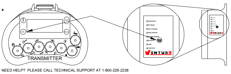
E-Stop
Probable Cause: Hitting E-Stop Button
- Twist E-Stop button clockwise until it “pops up”
- Press “Horn” toggle switch UP to start
- Observe display for HOME SCREEN
Probably Cause: Lost Communication (>0.5 seconds)
- Try re-establishing communiction
- Walk toward receiver
- Watch for normal operating screen
- Press “Horn” toggle up to reset main contact
Probable Cause: Loss of power to either RX or VCM
- See “NO POWER” solutions above
A2B Error
Probable Cause: Tripped compact A2B sensor
- Press “OK” button
- Lower the load away from compact A2B
Over 80% Load (Reduced Speed - All Functions)
Probable Cause: Load is Greater than 80%
- Check load chart for Load-to-Angle
- Increase boom angle
- Lower load, reposition vehicle, lift with…
- Shorter boom
- Increased boom angle
- Continue to operate crane at reduced rate (75%)
Probable Cause: Boom angle too low to lift load
- See “Load is greater than 80%” solution above
Probable Cause: Boom length too long for lift
- See “Load is greater than 80% solution above
Over Error (Reduced Speed - Winch Down, Boom In, Boom Up & Rotate Functions Only)
Probable Cause: Load is greater than 100%
- See “Load is greater than 80%” above, solution #1
- See “Load is greater than 80% above, solution #2
- Only the functions below are allowed for solution #2
- Winch Down (WD)
- Boom In (BI)
- Boom Up (BU)
- Rotate Left/Rotate Right
- Only the functions below are allowed for solution #2
Out of Level 4.5° - 6.5° (Reduced Speed - All Functions)
Probable Cause: Vehicle out of level
- Continue to operate crane at 75% speed
- To obtain full speed, see “Out of level > 6.5° ” below
Out of Level > 6.5° (Reduced Speed - Winch Down, Boom In, Boom Up & Rotate Functions Only)
Probable Cause: Vehicle out of level >6.5°
- If not in stowed position, stow crane
- Turn off crane / VLC system
- Completely retract stabilizers / outriggers
- Disengage PTO
- Disengage parking brake
- Reposition vehicle to solid level ground
- Engage parking brake
- Engage PTO
- Deploy outriggers / stabilizers
- Turn on crane/ VLC system
- Note message on transmitter display
Lost C-A-N Communications
Probable Cause: VCM / Boom Angle Sensor / Level Sensor
- Check connections of VCM and sensors
- Try re-establishing communication
- Approach receiver & watch for normal operating screen
- Press “Horn” toggle up to reset main contact
Pressure Sensor Error
Probable Cause: Pressure Sensor 1 / Pressure Sensor 2
- Remove Dins and check connections
- Check for hydraulic leaks
Service Crane Boom Stuck Mid-Air
Hydraulic Crane Manual Override
Venturo’s hydraulic cranes are available in two [2] general configurations: Proportional and Non-Proportional. The Non-Proportional configuration (see fig. 1) utilizes a safety shut-off valve which, when not actuated, allows hydraulic fluid to bypass the valve bank and return to tank; the crane will not function when the safety shut-off valve is not actuated. When the safety shut-off valve is actuated (control pendant energizes the coil or the coil is manually overridden), hydraulic fluid cycles through the valve bank and allows the crane to function. The Proportional configuration utilizes a proportional valve which, in its fully closed and fully opened positions, functions similarly to the safety shut-off valve, but adds the ability to operate the crane at any speed in between these two extremes.
In both the Non-Proportional and Proportional configurations, the four [4] crane functions (winch, rotation, boom elevation, and boom extension) are controlled by four [4] separate valve sections. Each valve section has two [2] solenoid coils (and two [2] manual overrides) which control the direction that the function operates (e.g. winch up vs. winch down). For a given crane function and direction (e.g. winch up), the solenoid coil and the associated manual override lie on the same side of the valve bank (both ‘push’).
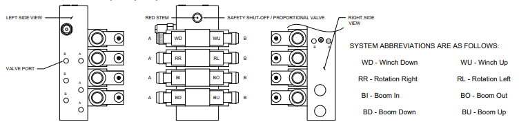
MANUAL OVERRIDE SYSTEM
Should an electrical failure occur, your Venturo crane can be operated manually. The manual overrides are intended for emergency use only and should not be used for normal operation.
To operate in manual override mode:
- Override the safety shut-off or proportional valve by turning the red stem on the valve as stated below:
- Non-Proportional System For override operation, press stem in and rotate counter-clockwise until it stops. To return to normal operation, press stem in and rotate clockwise until it stops.
- Proportional System For override operation, rotate stem clockwise (the farther the stem turns, the faster the crane operates). To return to normal operation, roate stem counter clockwise until it stops.
- Determine the coil / override associated with the function you wish to operate, then insert a small diameter object (an Allen wrench works well) into the detent on the end of the valve stem and press firmly. For example, pushing the stem labeled ‘A’ on the first bank (refer to illustration in Fig. 1) will actuate winch down.
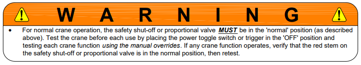
EMERGENCY STOP
In the unlikely event that a function of the crane does not stop once the function’s toggle switch is released, the Non-proportional crane can be stopped by simply toggling the power switch to the off (emergency stop) position, and the Proportional crane can be stopped by releasing the trigger.
Electric-Hydraulic Crane Manual Override
Each valve station incorporates [2] hydraulic ports and [2] coils. Manual override shafts are located in the center of the coils (See Fig. 1). Manual override decals are placed on each crane near the valve assembly. These decals provide a visual aid that helps the operator determine the function designations (Reference Fig. 2).
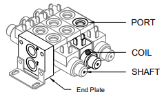
Fig. 1
Fig. 2
ALWAYS BE SURE TO CHECK HYDRAULIC OIL LEVEL BEFORE PROCEEDING. IT IS RECOMMENDED TO REMOVE ANY ITEM(S) THAT MAY INTERFERE WITH OPERATING THE CRANE MANUALLY. IF POSSIBLE, STRAPS AND/OR HARNESSES SHOULD BE REMOVED BEFORE OPERATING A CRANE IN MANUAL OVERRIDE !!
Procedure:
- Turn Master Disconnect switch to “ON”
- Power up the pendant / radio
- PENDANT – twist EMERGENCY STOP button clockwise
- RADIO – Press green ON button
- On the crane, reference the function you wish to perform using the manual override decal
- Using a tool with a diameter of 1/8″ or smaller, press the shaft inward and hold
- Reference the functions listed on your pendant or radio (See Fig. 3)
- Press the switch or button for the same function
- If you need to change function:
- Release switch or button
- Remove tool from shaft
- Go to step 3
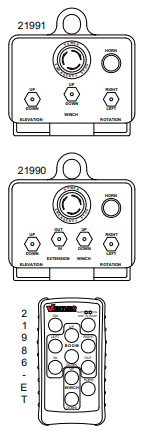
Fig. 3